- Emlid Reach Kit Contents
- Setup Materials
- Connecting to Reach Module
- Updating Reach Module
- PPK Configuration Setup
- Testing Reach Module
- Base Station Data Collection
-
Base Station Post Processing
-
Reach / Pixhawk Integration
-
Rover Data Collection
-
Rover Data Post Processing
-
Image georeferencing
- 2 x Reach Module
- 2 x Tallysman TW4721 antenna
- 2 x DF13 to DF13 straight cable
- 2 x DF13 to jumper wire cable
- 2 x Micro-USB to USB cable
- 2 x Micro-USB Female OTG cable
- Computer with Admin rights, internet access, and a wifi
network card.
- Wifi network with password and corresponding network
protocol (i.e. WEP,WPA,...)
- 1 free USB port on computer
- 1 free wall power receptacle near your computer
- USB wall outlet charger (any phone wall charger with an USB
plug and output of 5 volts). Most phone charges with an USB port
should work.
- Masking tape and marker (used to label Reach Modules)
- Power your Reach module with a micro USB cable.
- The Reach Module should begin flashing red, blue, and green
on the same face as the Micro-USB port.
- Once the Reach Module led shows a solid green led, the Reach
Module has begun hosting its own wifi network.
- The created wifi network will be named "reach:37:97" or
something very similar and always will begin with "reach:".
- Connect your computer to the newly created Reach wifi network.
The password should always be "emlidreach" with no spaces.
- Once connected, your computer will notify you that the network
has no internet access. This is ok as the Reach Module only
uses wifi as a way to host its own application.
- Open your browser and go to 192.168.42.1:5000.
- This should take you to a page with Intel and Edison Setup in
the title.
- Under the Change Device Name section next to New Device Name:
type in "Rover_Reach".
- Under the Connect to a Wifi Network section next to Network
Name: type in the name of the wifi network you have access to
exactly as it appears under the computers wifi network settings.
- Just below Network Name should be Network Protocol: where you
should select the appropriate option given the type of protection on
your network.
- Note that if you select any network protocol other than "Open" a
new bow will appear under Network Protocol named Password: prompting
you to enter your network password.
- Once you have the correct data entered in all of the prompt
box's
hit the "Submit" box. The page should refresh with the title Leaving Setup and a
progress bar will begin to build. The progress bar will begin as green as it grows from left to
right across the screen.
- Note that the Reach Module has been
renamed and now host a unique address, http://Rover_Reach.local, as
shown on the page as a hyperlink. Please take note of this
name for future use.
- Near the end of the progress bar, right side of the screen, the
bar will turn red. This is expected as the firmware loaded
onto the Reach Module is different to what the onboard Intel Edison
chip is use to seeing.
- Directly under the progress bar you will read "Sorry, could not
reach your device". This is indicating that the custom
firmware has been loading and your Reach Module is ready for use.
- Unplug and repower the Reach Module to force it to restart.
It should begin blinking a combination of red, blue, and green
lights.
- Once the Reach Module shows a solid green light for a few
seconds, it will be connected to the wifi network you entered in
step 14.
- Open a new tab in your internet browser and type in the unique
address created and shown in step 19.
- The page should be directed to the Reach View App. This is
how you will communicate to all Reach Modules when collecting data.
- Now that we have the Reach Rover setup we need to repeat the
above steps to setup the Reach Base.
- Following steps 1-12 exactly will take you back to the Intel
Edison Setup page.
- Continuing on step 13, we will name the 2nd Reach Module as
Base_Reach in the New Device Name prompt.
- Continue exactly as before with the remaining prompts.
- When finished, hit the "Submit" button. The page will
again automatically refresh with the title Leaving Setup and the
progress bar will continue as before.
- Again note the new name of your Reach Module,
http://Base_Reach.local, to
the upper right of the progress bar.
- When the progress reaches the far right of the screen and states
"Sorry, could not reach your device" you have completed the setup.
- Repeating steps 22-25 will ensure the Base Reach Module is ready
to begin data collecting.
- Note: Both Reach Modules may be used as either a base
station or a rover on your aircraft. We named them Rover and
Base to help differentiate the in the field and any 5 letter name
you wish may be used.
- Stick masking tape on each Reach Module. Use a marker to
name them Base and Rover to identify them in
the field.
- If you wish to know the IP addresses of each device, we recommend
downloading a free application called "FING" from your smart home
app store. It will allow you to view all devices connected
over your wifi network and gives their individual IP addresses.
- Each Reach Module will also have an individual IP address you
may type in to your internet browser instead of the .local address
when you are working over a your wifi network. If you use a
mobile device when configuring a Reach Module, an IP address tends
to be much easier to use.
- Power up on or both Reach Modules via a 5 volt power source such
as a phone charger within range of the wifi network used to set the
modules up in the previous part. Note, the Reach Module needs
a wifi network with an active internet connection to update.
- Allow each Reach Module to cycle through the red, blue, and
green led sequences until a solid green led is shown for a few
seconds. The solid green led indicates that the Reach Module's
wifi chip has connected to a known wifi network.
- Launch the internet browser on your computer and type in
the name created during initial setup (
http://Rover_Reach.local or
http://Base_Reach.local ) or
the IP address you obtained using the FING app on your
smartphone.
- Once connected you should see the Reach View App on you screen
with 4 different tabs on the top; Status, Config, Logs, and finally
settings represented by a gear symbol.
- Click the gear symbol on the far right to enter the settings of
the Reach Module.
- You should see two gray blocks once the settings page has
loaded.
- Click the "Update" button on the second gray block labeled
"Current Version: v #.#.#" to begin updating your Reach Module to
the latest version. More than likely your Reach Module will be
shipped to you out of date.
- A countdown timer will appear to the right of the button.
Allow the timer to count all of the way down and wait for a prompt
telling you to refresh the page.
- Refresh the webpage and click back onto the settings gear
button.
- Your Reach Module should now have much more options under the
settings tab including; Network, Bluetooth, Rinex Version, ReachView
Version, Reach Image Version, and Reboot.
- Ensure the following are at the current versions before
proceeding to the next step.
- Rinex Version: 3.01
- ReachView Version: v0.4.9
- Reach Image Version: 1.2
- If any of the 3 Versions are below what is listed please make
the appropriate changes are made and reboot the module using the
"Reboot" button at the bottom of the settings page.
- Once both Reach Modules are updated, you may move on to the next
part.
- Power up and connect to your Reach Module via the steps in the
Updating Reach Module section above.
- Open your computers web browser and connect to the Reach Module
using its unique address or IP address.
- Once connected and on the ReachViewApp click the Config tab
found on the top middle of the page.
- On the Config page, click on and select the Rover box.
- Next, click the dropdown arrow and select the
"reach_single_default.config" option.
- Moving down the page you will see a verity of new option. These
options should match as given below:
- Position Mode: static
- Used positioning systems: gps, sbas, glo
- Dynamics model of the rover(kinematic and dgps only): off
- u-blox configuration file: GPS_GLONASS_5Hz
- Input source for base corrections: off
- Input format for base corrections: rtcm3
- Solution 1 output path: file
- Solution 1output format: llh
- Solution 2 output path: off
- Solution 2 output format: llh
- Raw data log for onboard receiver: file
- Raw data log for base corrections: off
- Base antenna coordinates: rinexhead
- Advanced settings should be left alone at their defaults.
- Once everything on the page matches the settings above, hit the
"Save" button on the top left on the screen. A window will pop
up titled "Save Config" with the question asking "Do you want to
load the current config after save?". Click yes and the window
will disappear.
- Note that the Reach Module will switch into collection mode.
You must hit the "Stop" button at the top left of the page to cancel
the data collection.
- You should be ready to move onto the next step.
- Move to an outside location while remaining in range of your
wifi network. You will need as much open sky as possible for
testing the Reach. Please avoid setting up under trees,
building overhangs, power lines, or any object that may interfere
with a GPS signal.
- Plug in the provided Tallysman TW 4721 antenna from the Reach
Kit into the antenna port on the Reach Module.
- Provide power to the Reach Module via a 5 volt source and the
Micro-USB port on the Reach itself.
- Once powered, the Reach Module should begin the usual sequence
of red, blue, and green flashes from the led. As before wait
for a solid green light to appear for a few seconds.
- After viewing the green led, go to your computer on the same
wifi network and connect to the Reach Module using your internet
browser and the address for the device.
- You will see the familiar ReachViewApp appear on your screen.
Click the Config tab and make sure the options you previously
selected from "PPK Configuration Setup" are still the same. It
is always go to skim through these options every time to ensure all
of your settings are correct to avoid wasting field time by having one
option incorrect.
- If all options look correct, click the "Start" button on the top
left of the screen.
- Once you have started the Reach click the "Status" tab on the
top left of the screen. This will give you a live view of
satellites the antenna can currently view.
- Next, click the "Logs" tab on the top right of the screen.
The data collected from the Reach is store in its onboard memory.
By clicking off of the Logs tab onto another tab and back to Logs
you are able to verify that the Reach is actually collecting data.
The file we are interested in it the Rover file and should be the
only file you will use. Note the time stamp to the left of the
Rover file under logs will more than likely not match that of your
time zone.
- After verifying that that Reach module is logging data under the
Rover file, please repeat steps 1-9 for the other Reach Module.
- You should now be ready to start collecting data in the field.
When preforming PPK data collection you must use a base station.
The base station location must either be on a known point (known
Latitude, Longitude, Height) such as a land survey control point or you
may create a base station point from any location with an open sky view.
It is recommended that all base station locations be in wide open areas
with as little sky with blocked as possible. Every tree, power
line, or building will limit and my skew your data. We prefer to
set our base station in open fields or on top of an elevated position if
possible. If you are trying to make an orthomosaic map, you may
use the base station data collection process to set ground control for
your photo. Later on we will show an example of a flight were the
process below was used to create ground control points for our
orthomosaic photo. Please also note that the objects listed above
along with water and even tall grass around your base station collection
point may introduce multipath problems when you move on to the post
processing steps.
Items Needed
- Laptop or smartphone with wifi card/ chip. Laptop is
recommended.
- 5 volt power source with a USB port. May use laptop or
smartphone.
- USB to Micro USB cable for powering from laptop
- Micro-USB Female OTG cable is powering from smartphone
- Ground Plane of at least 120mm x 120mm square
- Tape for holding down Reach Module if windy (non metallic)
- Either Reach Module may be used for collection
- A ground plane of at least 120mm x 120mm should be used along
with the Tallysman 4721 antenna from the Reach Kit. The
company that creates the Reach Kit has some in-depth forum post
covering the topic of ground planes and their sizes
Emlid Forums
- Once you have decided on a ground plane and mounted the antenna
on it, place the ground plane/ antenna setup on your chosen base
station location. Remember if possible to pick a location that
will fall within the orthomosaic photo if you are going to fly one.
Note that base station locations may be used an endless amount of
times and allow you to quickly collect field data later after the
base location has been determined.
- Once the ground plane and antenna or in a good location,
carefully connect the antenna male end into the female end on the
Reach Module. You may want to use some sort of tape to hold
down the ground plane if you are collecting in windy conditions.
The Reach Module should not be on the ground plane as the antenna is
the only device collecting the GPS signals.
- Next, power the Reach Module using a 5 volt power source.
It is best to use a power source the enables you to power the reach
from the Micro-USB port as the DF-13 plugs can be damaged easily.
- Once powered, allow the Reach Module to run through its red,
blue, and green led flashing sequence until it shows a solid green
light for several seconds. This can take up to 60 seconds or
longer as the Reach is looking for a known wifi network to
communicate with.
- Unlike the setup processes before you will be working off of the
Reach Module's own hosted wifi network. The Reach only creates
a network for communication purposes and does not actually allow you
to surf the internet.
- The Reach hosted network should become available once the green
led lights up for several seconds. On your computer select
view wifi network and look for a new network called
Base_Reach:37:97. The numbers following the ":" may be
different for you. once you connect you will be prompted for a
password. As before the password should always be "emlidreach"
all one word.
- After connecting you should open up your internet browser on
your phone or computer. Once connected type in "192.168.42.1"
into the web address and hit search. Note that you must be
connected to the Reach hosted network or you will just return a
search for the IP address.
- If done correctly the ReachViewApp should appear on screen.
This should look familiar from the previous steps above.
- Now click the Config tab and as before, check all options
to make sure they match those from the "PPK Configuration Setup".
- If correct, click the start button and then click the "Status"
tab. You should see satellites start to appear and show yellow
and green bars in the graph. Note that the numbers on the
screen will continually change and should not worry you.
- Click the "Logs" tab to ensure a new log file has been created.
Click off the Logs tab onto either Status or Config and back to the
Logs tag to make sure the log file is growing in size.
- If the Rover file under the Logs tab is getting bigger you have
correctly set everything up.
- The longer you let the Reach Module collect data on a single
point without being disturbed, the more accurate the data will more
then likely be after processing. A good time frame is to allow
the Reach Module to collect data from at least 30 minutes.
Later on we will go over flying missions while collecting base
station data simultaneously.
- Once you feel you have collected enough data go back the to
Config tab and click the "Stop" button to stop the Reach Module.
Make a note of the time stamp and date of the Rover file you have
just collected. You may remove power from the Reach Module and
head back to the office or repeat the process on another base
station location for later use.
Along with a step by step workflow on how to process your data, we
will also provide an example data set files you to work along with.
This should allow the user to practice and compare their own workflow to
that of a known data file set to ensure the understanding of the steps
below. Understand that some of the data you will need to complete
this process is provided by government entities and may take up to 24
hours to post to their website.
Items Needed
- Computer with wifi internet access
-
RTKPOST and RTKPLOT from the Emlid website (ver2.4.3 b16)
- Configuration files for RTKPOST
- Reach Module you collected the base station data with
- 5 volt power supply with USB to Micro-USB
- Program such as 7zip or winrar to extract compressed folders
- Power up the Reach Module with a 5 volt power supply via the
Micro-USB port.
- Allow the Reach to cycle through the red, blue, and green led
lighting sequence until it shows a solid green led for a few
seconds.
- Open your internet browser and connect to the Reach using its
unique IP address.
- Once connected, click on the Logs tab to the upper right hand
side of the screen.
- Find the Rover log from the correct time and date you collected
the base station data from.
- Now you click on the word Rover and allow the Reach to convert
your base station data to a Rinex file. Once the download is
complete you should see a .zip file in the download folder of your
computer. (Ex: rov_201610042242.zip)
- Now you need to set up a working location for all of your Reach
files. For this example we will just use the desktop.
- On your desktop, right click and create a new folder.
Title the folder Reach_Logs. Once created, open the folder and
create a new folder with the title of the date you collected the
data (ex. 10_04_2016). Now open the dated folder and create one more
new folder dated Base. This may seem like a lot of work for
one set of files, but once you start collecting a larger number of
file set you can easily become inundated with data.
- Go back to the download location of your Rover .zip file.
Right click the file and extract it to the Base folder you created
at the end of step 8.
- Under items needed above you should see a hyperlink that takes
you to the Emlid website. This webpage will display to
programs you need to download. The first being RTKPOST which
you will use to process the collected data and secondly a program
titled RTKPLOT which as the title suggest plot the processed data.
Open both of these programs and ensure you are running ver2.4.3 b16
for both programs as shown on the top bar of each.
- Now you will need to go back to your internet browser to collect
two different sets of data. Depending on what country you live
in, you may have to go to different website. We will be
working under the idea that you are in the United States but will
also cover what to do if you are outside of the USA.
- First you will need to find the closest Continuously Operating
Reference Station (CORS site) to the area you collected your base
station data. In the USA the National Geodetic Survey (NGS)
under the National Oceanic and Atmospheric Administration (NOAA) run
such sites across the USA and several other countries. Most
countries around the world have such site run by the government and
should be free of charge to use.
- Click here to go to
the NGS CORS site map. Once the page has loaded,
find the location of the closest CORS site to where you collected
your base station data. We will be using the CORS site
TXBO which is located on the Northern side of Boerne, Tx and
within 10 Km of the location we collected our base station data.
- Once you find the closest site, click on the site location name
in the pop up window. This should redirect you to the CORS
site page. On this page you may find all types of data
available on the site in question. On the left hand side find the
link labeled Standard Files and click the link. You will be
redirected to another page again showing all of the sites NGS runs
titles
CORS Data- Standard Download.
- On this page, select the appropriate options for the site ID you
selected in step 13 under the column titled SITE. Under the column
titled OPTION select RINEX Data. Finally on the far right of
the page, select the appropriate options for the year, month, and
day you collected the base station data. Note that CORS data
will not be available until the following day. For our
example, we will use the follow; site:TXBO, option: RINEX Data,
Year:2016, Month: October, and Day: 04.
- Once you fill out the page to match the data and site location,
click the find files button at the bottom center of the page.
You will be redirected to a page with a large list of file.
This page will list several different file types, we will be focused
on finding the .16o.gz file. This file contains a days worth
of data collection from the CORS static site. Think of it as a
base station you are comparing your own base station location to.
For our example we will click and download the file titled
txbo2780.16o.gz.
- As before with the Rover file from the Reach Module, the CORS
site file is a compressed file type that will need to be unpacked.
Find the .16o.gz file on you computer you downloaded in step 16,
right click it and then send it to the folder you labeled with the
date. Make sure to send it to the dated folder and not inside
of the Base folder.
- Now you need to download precision clock data from another site
run by International GNSS Service (IGS). Like the data
collected from the NGS CORS site, IGS takes up to 24 hours to post a
rapid solution. You must know the GPS day to correctly find
the date you will need from IGS. Go to the website linked
HERE to
find the GPS date of your collected data. for example, the date we
are using is October 04, 2016. We find the date on the
calendar and take note of the first row (1917:2). The first 4
digits mark the GPS week (1917)we fall in followed by the day of the
week (2).
- Now click the link
HERE
to go to the IGS website that contains recent clock data broken down
by weeks and days. Find the correct week and day as we found
in step 18, then click the date that matches your collection date.
The downloaded file will be a .sp3.Z file type. For our
example we will be using file igr19172.sp3.Z (downloaded files name
should match your GPS date from step 18). Note that you may see
files on this page before they are fully ready for use. We
recommend waiting for RAPID solutions to post and avoid using others
such as ULTRA unless you have experience doing so.
- As before, the .sp3.Z you downloaded is a compressed file type
and needs to be extracted. Find the downloaded .sp3.Z file and
extract it to the dated file you created previously.
- Now you are finally ready to process your collected base station
data. Find and open the RTKPOST.exe you downloaded from the
Emlid website (ensure the header says RTKPOST ver2.4.3 b 16).
You will also need the configuration file labeled
BaseCorrection.conf.
- Once opened, click the Options button on the bottom right of the
screen. In the pop up window click the load button. Now
find the file provided labeled BaseCorrection.conf. This
should load settings you will need to correctly process your base
station data. Go through and double check that the settings
under each tab match those of the pictures below. If they
match you may move on too the next step. If not, please make
the correct changes. Hit the OK button to use these settings.
- You should now be back on the main page of RTKPOST. In the
first row click the box to the right with the three dots to open the
file explorer. Once opened, find the Base folder you extracted
the Rover data to in step 9. Open the RINEX folder and inside you
should see a .obs (ex. rov_201610042242.obs). Select the file and
hit open. You will now see a directory link to the file you
just selected in the first row.
- Moving down to the second row, we need to select the .16o file
we downloaded from NGS. Again click the box with the three
dots to open the file explorer, open the dated folder, selected the
.16o file we extracted earlier (ex. txbo2780.16o).
- Moving to the third row, you now need to find the navigation
file or .nav from the base station data. Click the box with
the three dots to open the file explorer, find the RINEX folder
inside of the Base folder again, and now you should see a similar
titled file as step 23 but with a .nav extension. Select
and open this file (ex. rov_201610042242.nav).
- Moving down to the forth row, you need to find the clock data
file or .sp3 file. Click the box with the three dots to open
the file explorer, find the dated folder, select the .sp3 file from
step 20. Select and open the file (ex. igr19172.sp3).
- You must now select and create a file location for your
processed solutions. The last row in RTKPOST tells the program
what to name the corrections and where to put them. Select and
delete any file name that RTKPOST may have generated automatically
in the last row. Now as before click the box with the three
dots to the right to open the file explorer. A box should open
with the title Output File. Make sure you are inside on the
Base folder. On the bottom of the page you will see a row with
the title File name:. Fill in the corresponding field with the
output file name you desire (ex. BaseCorrections). Now hit the save
button.
- You should be back on the main RTKPOST page. You are now
ready to process the data. Hit the Execute button and allow
RTKPOST to run through the data. Note that you are only using
a small portion of the GPS clock and NGS CORS data. RTKPOST
will more than likely say (Not Responding) on the top. This is
ok as the program is still running. Within a few minutes of
hitting the Execute button, a green status bar will appear on the
bottom of RTKPOST.
- Once RTKPOST has completed processing, the top of the status bar
will say Done. You may now click the Plot button on the bottom
right of the window.
- RTKPLOT should open automatically when you click the Plot button
in RTKPOST. Once in RTKPLOT, click view and then options.
You will need to change a few settings before proceeding. In
the Options window that appears, ensure that all of the settings
match those of the picture below. The most important option
being Coordinate Origin: Average Position. This will take an
average of the points collected and output an average location for
you to use. If done correctly, your data should fall within a
few cm's square, or if using the example data, an area of 3mm x 5mm.
- You are looking for a tight group of green dots on your plot.
Green dots represent a fixed location after corrections have been
applied. If you are showing something other than green dots
(yellow or gray) we will go over several options for you to take
under the tips section.
- Back on the main page of RTKPLOT you should see a group of data
in the upper right side of the window. ORI = is you calculated
base station location that has been processed. (ex. ORI =
29.889322478 N, 98.819829697 W, 254.4809 m)
- You can use the ORI = as your base station location. You have
completed the base station data processing steps.
Base Station Data Processing Tips
- RTKPLOT will visually show you the health of the data you
collected for you base station. There are three colors of dots
RTKPLOT uses; Green (Q=1) fixed location, Yellow (Q=2) float
location, Gray (Q=5) bad location data. If RTKPLOT displays
any color other than green dots you have several options.
- You may go back the RTKPOST and rerun the data set with a
different elevation mask. The default one you use is 15
under the BaseCorrections.conf file. Go back to RTKPOST,
click the Options button on the bottom, under the Settings 1 tab
change the Elevation Mask from 15 to 10. Hit ok to close
the options and hit the Execute button on the main page of
RTKPOST. If it doesn't improve the data trying using
different Elevation Mask until you get obtain results. (ex. 10,
20, or 25).
- Look to see if the bad data is at the beginning or end of
the collection data set. If so you can change the start
and end times of RTKPOST at the top of the main page.
- Worst case scenario is that you will have to repeat the base
station collection process. You may need to pick a better
location for your base station or switch to a better ground
plain to prevent multipath. Try to avoid setting up near
water, tall grass, and areas with large sections of the sky view
blocked.
The sole purpose of the Reach Module on an aircraft is to
capture precise event location when a camera is triggered. You
will not be using the Reach for any flight navigation. To that
end, the Reach is only going along for the ride and we do not intend on
you using it for any other purpose.
Items Needed
- Find an open AUX servo plug on the end of the Pixhawk.
Make sure to only use one of the AUX OUT plugs and insure that there
are now signals being set to it from the Pixhawk (found under Full
Parameter Tree in Mission Planner).
- Find the end of your Reach hot shoe time mark cable with the
male serve plug. Insert it into the open AUX OUT port you have
chosen to use in step 1. Note the black wire or (-) should be
on top and not the white wire.
- Insert the hot shoe circuit board with the small pin facing
towards the camera into the cameras hot shoe adapter. Be
careful when inserting and removing hot shoe circuit board as the
small pin may hang up sometimes.
- The remaining end of the Reach hot shoe time mark cable has a
DF-13 6 pin connector on it. You must pay close attention when
inserting or removing this plug into a Reach Module as it is very
easy to damage the Reach. Find the DF-13 6 pin plug receptacle
on the side of the Reach Module with the Intel Edison chip. It
should be the side of the board with only one plug on the entire
face and insert it carefully.
- Take the Tallysman TW 4721 antenna and adhere it to the ground
plane you will be using for your aircraft. Ensure is it secure
to avoid it come detected and becoming damaged in the motor
propeller. Once you have it attached, take the end with the
pin and connect it to the appropriate port on the Reach Module.
- Place the Reach module in a safe and secure location within the
aircraft. You do not want to Reach to become unplugged or
damaged while in flight.
- Power up the Pixhawk and ensure the Reach Module is receiving
power.
- You have completed the Reach / Pixhawk integration
Before moving onto using a Reach Module on a moving
vehicle, ensure you completely understand the procedures needed to
correctly collect and process base station data. You must always
have a base station running when using a Reach Module on a moving
vehicle as the data collected from a Rover unit will need to be
processed against a base station at a known location. It is ok for
you to set the base station up on an unknown location and later on
determine a precise location while at the same time using a Rover.
Also note that the base station must be up and running before you start
recording any data from the rover and the base must keep collecting data
the entire time the rover is running to obtain a fixed location.
It is recommended that you fly several times without a camera payload to
ensure you completely understand the process. Please skip the
steps covering the camera if you are flying without a payload.
Items Needed
- Laptop or smartphone with wifi card/ chip
- 5 volt power supply for Reach base station
- Ground plane for both Reach base and rover
- Tuffwing - Reach hot shoe time mark cable
- Set up your base station on a known or unknown location and
ensure that it has a good sky view. If the sky view is block
in any way, you risk recording data that may impact the rover from
holding a fixed location. Several notes are below when picking a
good base station location.
- Always have a good sky view. This can not be stressed
enough and most people do not understand that the smallest
objects such as tall grass around your base station may cause
multipath issues. Multipath = bad results.
- Set up the base station on an elevated position if possible.
You may want to set up you base station on a survey tripod or
the roof of a vehicle.
- Use a good size ground plane. Mentioned in step 1 under
Base Station Data Collection, there is a link to the Emlid
forums going over ground planes.
- Ensure your base is collecting data well before (5-10
minutes) you start the rover and begin collecting data with it.
- Continue running the base station throughout and after the
rover is done collecting to ensure you have base station data
for the entire run of the rover.
- Now that you are sure the base station Reach is running, you can
move onto the Reach rover. Following the setup from Reach /
Pixhawk Integration, ensure both your Pixhawk and Reach are running.
This includes connecting to the Pixhawk via mission planner and
going over your vehicle controls.
- Allow the Reach Module to power up and begin the red, blue, and
green led flashing sequence. Once it has held the a solid
green led for a few seconds it will be ready to connect to.
Note that if you are in the field and away from a wifi network, the
Reach Module will begin hosting its own wifi network. We will
be working off the assumption that you are in the field and away
from the wifi network you set the Reach's up on.
- Connect to the Reach as you have before. If the Reach is hosting
its own wifi network you will need to connect to the network named
Rover_Reach: 37:97 or something very similar. Note the
password should always be "emlidreach" all one word. If you
are within a wifi network that the Reach has been set up on
previously, you will have to connect to the devise using its unique
IP address.
- Once connected open your internet browser and search
"192.168.42.1:5000". This should open the ReachViewApp which
you have used previously.
- After connecting to the ReachViewApp, click the Congif tab in
the top center of the page. Under this tab you should see all
of the settings from PPK Configuration Setup. Double check
that all of your setting match as below.
- Rover is selected in the upper right hand side of the screen
- The first dropdown below Rover should have
"reach_single_default.config" selected
- Position Mode: static
- Used positioning systems: gps, sbas, glo
- Dynamics model of the rover(kinematic and dgps only): off
- u-blox configuration file: GPS_GLONASS_5Hz
- Input source for base corrections: off
- Input format for base corrections: rtcm3
- Solution 1 output path: file
- Solution 1output format: llh
- Solution 2 output path: off
- Solution 2 output format: llh
- Raw data log for onboard receiver: file
- Raw data log for base corrections: off
- Base antenna coordinates: rinexhead
- Advanced settings should be left to their default settings
unless you are an advanced user.
- If all of you setting match those above, you should be ready to
start collecting data.
- In your mission planning software ( we will assume Mission
Planner), load your flight path with all of the necessary takeoff,
waypoints, and landing positions.
- If you are flying with a payload (camera) make sure that all of
your exposure settings are set up before hand. Changing
settings on your camera while the Reach hot shoe time mark cable is
connected can be cumbersome.
- Move the vehicle into an open area with a good sky view.
If you feel it is at a decent location, set the vehicle down on the
ground. Go back to your device running the ReachViewApp. If
you are ready to begin, hit the start button on the top left side of
the screen.
- Allow your ground vehicle to sit stationary for at least 5
minutes to gain a good fix of its own location. It is in good
practice to allow this process to take place to ensure that both the
base station Reach and rover Reach on your vehicle are viewing the
same satellites. Its much easier to work with good data than
to fiddle with it during post processing back at the office. A
good indication of a fixed vehicle position is to watch for changes
on the status page. After about 5 minute, you will see little
changes in the latitude, longitude, and height. You should
also see a majority of green status bars on the page.
- Once you feel the vehicle has gained a fixed position you are
ready for flight. Make sure the camera is turned on and ready
to begin taking pictures. Go over any pre-flight checks on the
aircraft. At this point you should be ready for flight.
- When preparing to launch the aircraft try to avoid standing
directly over or in the way of the Reach antenna as you may disrupt
the GPS signals. Set your vehicle into autonomous mode and
launch the mission. At this point the aircraft should preform
the mission you uploaded to the aircraft in step 8.
- Upon completion of the mission and once your aircraft is on the
ground, reconnect to the Reach rover using the ReachViewApp via
laptop or smartphone. Once connected, go to the Config tab and
click the "STOP" button on the top left of the screen. This
will leave the Reach Module on but tell the unit to stop collecting
location data. You may now power down the Reach Module as well
as your aircraft.
- You may now move back over to the base station Reach to shut it
down. As before in the Base Station Data Collection portion of
the tutorial, it is recommended that you collect position data no
less then 30 minutes at your base station location. Even If
you are setting up on a known point from previous data collection,
it is a good way to ensure you have enough sample data to run your
base station location again if problems should arise.
- Connect to the Reach Module that you are running as a base
station using the ReachViewApp and the devices hosted wifi.
Once connected to the ReachViewApp click the CONFIG tab then click
the STOP button in the top left side of the screen. This will
tell the Reach to stop collecting location data.
- You may now power down the Reach Module. All that is left
is to post process the collected data.
In the following steps you will learn how to take the data collected
in the field and apply corrections similar to the steps followed in the
Base Station Post Processing tutorial. We will assume you
understand how to calculate the base station location using the
previously mentions tutorial and move on to correcting the rover
location and obtaining time marks for the photos taken during flight.
If you are practicing or just trying to obtain a corrected flight path
for the aircraft please ignore the steps discussing time marks as you
will not need to use them. Note that the word ROVER is used
interchangeably as that is the name of the file created from both Reach
Modules. When the work is completely capitalized it is pertaining
to the log file and not the Reach Module used as a rover.
Items Needed
- Computer with wifi internet access
- RTKPOST and RTKPLOT for the Emlid website (ver2.4.3 b16)
- Configuration files for RTKPOST
- Reach Module used as base station
- Reach Module used as rover on aircraft
- 5 volt power supply with USB to Micro-USB
- Program such as 7zip or winrar to extract compressed folders
- Power up the Reach Module you used as a base station in the
field. Allow the module to run through the red, blue, and green led
light sequence. Once the green led is shown for several
seconds, the module should be connected to the wifi network.
Note we are assuming you are working on the same network as the one
you originally configured the Reach devices on. If not you
must connect to each individual device as you did in the field using
the Reach's hosted wifi network.
- Connect to the ReachViewApp after allowing Reach Module to
finish its booting sequence. As before you will see the
Status, Config, and Logs tabs on the top of the screen. Click
the Logs tab and allow the files to fetch.
- Once the files appear, find the appropriate ROVER log from the
Rover Data Collection. Click the ROVER file and allow the Reach
Module to convert the file into a RINEX file. This may take
some time as the files are usually over10 mbs. The file should
automatically download to your computers download folder.
- As before you will need to follow the steps used previously in
the Base Station Data Processing tutorial. We will assume that
you are working from your computers desktop, but any location you
would like will work.
- Go the your computers desktop, right click, and create a new
folder. Label the new folder the date of your flight.
Open the folder and create two other new folders and label them Base
and Rover respectively.
- Go back to the location of the ROVER RINEX file you downloaded
from the Reach Module used as a base station. Once you have
found the file, right click it and extract the file using an
extraction program of your choosing. Make sure to direct the
file extraction program to the Base folder you created in step 5.
- Once extracted, go to the Base folder and ensure you have done
everything correctly. You should have a folder labeled RAW, a
folder labeled RINEX, and a readme.txt file. If for any reason
the files do not show up, clear all of the data out of the Base
folder and re-download the Rover file from the Reach and repeat the
above steps.
- Now unplug the Reach Module used as a base station and switch it
with the Reach Module used as a rover on the aircraft. As
before allow the Reach to cycle through the red, blue and green leds
until a solid green led appears for a few seconds.
- Connect to the Reach Module as before using the ReachViewApp,
click the Logs tab, find the correct ROVER file from the flight, and
click the file to begin converting it to a RINEX file.
- After the conversion and download to your computer is complete,
right click and extract the ROVER file to the Rover folder created
in step 5. As before make sure the file extracts correctly.
You should have a folder labeled RAW, a folder labeled RINEX, and a
readme.txt file. If for any reason you are missing any file,
clear the Rover folder and repeat step 9 and the beginning of step
10.
- If you had the base station set on a known location with
coordinates in WGS 84 or the coordinate system you will be working
in then you should not need to process your base station location.
Where to input the base station coordinates will be shown later on
in the tutorial.
- If the base station was set up on an unknown location, you will
need to follow the steps from the Base Station Post Processing
tutorial from above.
- Assuming you have calculated your base station location you may
move on to processing your flight and camera locations.
- Open up RTKPOST (ver2.4.3 b16) and clear any files from the
input boxes to avoid using the wrong data. (pic 42)
- In the first box locate the Rover observation file (.obs),
Rover> RINEX> .obs.
- In the second input box down find and select the Base
observation file ( .obs), Base> RINEX> .obs.
- In the third box input down you will need to find and select the
Base navigation file ( .nav), Base> RINEX> .nav.
- If you have the GPS clock data file from IGS on the day that you
collected the Rover data you are processing, you may find and input
it into the forth box from the top. Although not necessary, it
will help in the processing of the data.
- With all of the data correctly selected, you now need to go to
the bottom input box and select an output folder for your flight
data. It is recommended to create this file inside of the
Rover folder. For example the root of a file would be:
10_04_2016_Rover_FlightCorrected.pos. Where 10_04_2016 would
be the date you flew (mm_dd_year), Rover would be inside the Rover
folder, and FlightCorrected would be the aircrafts path corrected
using the base station data. Note that the corrected flight
path may be named anything of your choosing.
- Once you have set the corrections file destination, click the
Options button on the bottom right in RTKPOST.
- Once the options window has opened, click the button labeled
LOAD. You will be using a new configuration file that is set
up to calculate corrections for a moving Reach Module against a
known base station.
- Download the RTKPOST configuration file for rover corrections
here.
- Load the RoverCorrection.conf file, Once loaded click the
Positions tab on the upper right of the options window.
- In the center of the window you will see a header labeled
Base Station. There will be a dropdown just below the header where
you will be able to select several different option. Since you
should have calculated the base station's location previously using
the tutorial from earlier you will need to select the
Lat/Long/Height (dem/m) option.
- The inputs below the dropdown box should now switch from a gray
color to white allowing you to input values. You should now
carefully input the values you have calculated previously for your
base station location. Once you have input the numbers and
verify all values are correct, you may hit the ok button on the
bottom of the window.
- If everything looks ok you may now run RTKPOST to begin
computing the flight path and camera location of your aircraft by
hitting the Execute button.
- Allow RTKPOST to run there the data. It may take up to 5
minutes and RTKPOST may read (not responding) at the top of the
window. This is expected as the program begins to look for
matching GPS clock data.
- Once RTKPOST has finished processing the data you may click the
Plot button on the lower left of the window to view the aircrafts
flight path.
- After clicking the Plot button, RTKPLOT should automatically
launch a new window. The new window should show you the flight
path of your aircraft. You are looking for a solid green
line for your flight path. Note that a green flight path means
you have a fixed location, a yellow flight path means the aircraft
was in a float position, and a black flight path means there were
not enough satellites matching from the rover and base station.
In the tips section below I will go over how to manipulate the data
if you return any flight other then fixed.
- Now go to the Rover folder and find the location you save the
flight path corrections file from step 19. In this location
you should also see a file with the same name with the addition of
_events.pos attached to it. This new file is the camera
location captured and processed out from inside the Reach Module you
were using as a rover on the aircraft.
- Go back to the RTKPLOT window that was opened in step 29.
Now click File> Open Solutions-2. Find the event file that you
found in step 30 and open it. This will overlay the locations
of the camera triggers on top of the aircraft's flight path.
- You should now be able to open both the FlightCorrected and
FlightCorrected_events by importing them into excel or opening them
using notepad for review.
- If you were using a camera during your flight, you should now be
able to open the events file and pull the latitude, longitude, and
height for photo geotagging.
Rover Data Post Processing Tips
- In the event that you do not obtain a fixed position during your
flight you have several options before going back out to the field
to recapture the data.
- Do not worry if the launch of the aircraft does not return a
fixed position. When flying fixed wing aircraft
especially, it is very common to lose fixed position on take off
and landings. The aircraft is more than likely flying very
fast and at extreme angles during these times.
- Go back to RTKPOST> Options > Settings 1 tab. Change
the Elevation Mask from 5 to 10, 15, or 20. This will
change to angle of satellites that the base station will use in
the correction process. By raising the elevation mask, you
are forcing RTKPOST to use only satellites directly overhead and
not off in the distance. The downside to this is that you
will lose more available satellites for correction.
Re-execute the data until you find an elevation mask value that
works best for you.
- Go back into RTKPOST and ensure you are using the correct
files from the flight and you have entered in the correct base
station location under the options.
- If you still have bad data go over all of the setup and double
check you are running the correct settings in the ReachViewApp.
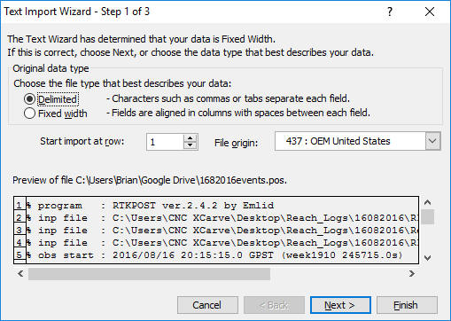
- Start Microsoft Excel and select File > Open.
- Navigate to the folder that contains the _events.pos file.
- Change Files of Type: to All Files (*.*)
- Select the .pos file and click Open.
This will start the Text Import Wizard.
- Select Delimited, then Next.
- Select Space, then Finish.
- Select the latitude, longitude, and height data.
- Paste them into notepad and save as a .txt file.
-
Here's how you georeference images using the latitude, longitude, and
height data in Pix4D.
|