Disclaimer
Please read this disclaimer carefully before using
the UAV Mapper. The UAV Mapper is an excellent flight platform offering
an excellent flight experience. Despite the UAV Mapper having a built-in
autopilot system and our efforts in making the operation as safe as
possible there are inherent risks when flying the UAV Mapper. Tuffwing
LLC accepts no liability for damages or injuries incurred directly or indirectly from the use of
this product.
Danger
Loss of RC signal will cause the UAV to enter
"Failsafe" mode - even when it is not flying. During Failsafe mode the
UAV will apply full power to its motor and attempt to fly to 100 meters
altitude and circle overhead. This presents a danger of a propeller
strike when servicing the UAV. Take the following precautions:
- Always remove propeller when servicing.
- The RC transmitter must be on and in FBW mode with the throttle down whenever the UAV is armed and on the ground.
- Keep RC transmitter 3 feet (1 meter) away from the UAV. Placing the RC transmitter too close to the RC receiver will cause loss of RC signal.
Contents
- Install the wings
- Install the camera mount
- Install Mission Planner
- Display RSSI in Mission Planner
- Calibrate the compass
- Connect a Reach module
- Flight modes
- Transmitter control check
- Autopilot control check
- Install the propeller
- Landing site requirements
- Create a take off and land mission
- Parachute landing
- Check LED status
- Test airspeed
- Check center of gravity
- Fly your UAV Mapper
- Create an aerial photography mission
- Slide the center spar into the body
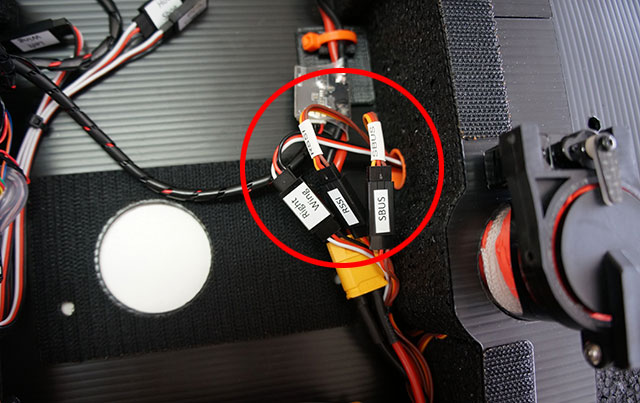
- Slide the left wing onto the center spar and feed the servo extensions into the body.
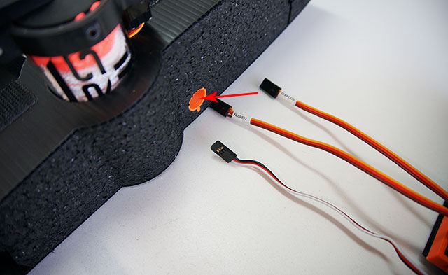
- Connect the RSSI, SBUS, and Right Wing servo extensions.
- Slide the left wing onto the center spar.
- Insert Set the GPS/Compass
into the left wing with the arrow on the compass pointing left.
-
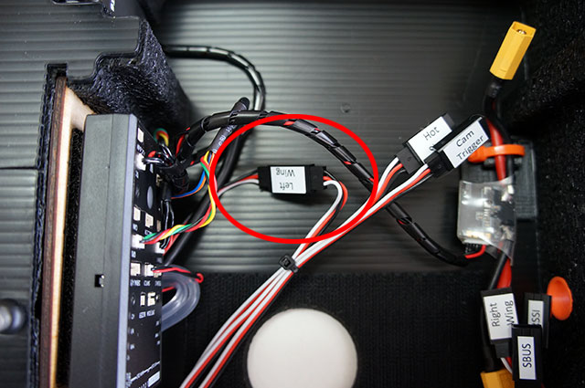
Insert the left wing servo
extension through the orange guide into the body.
- Connect the left wing servo extensions.
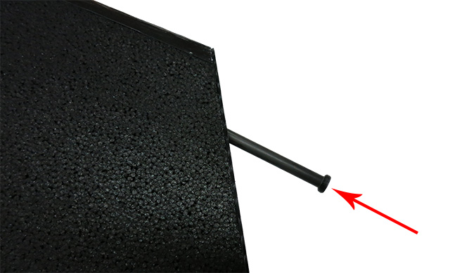
- Slide the wings to the body and push in the leading edge spar.
- Set the camera mount onto the Velcro base.
- Connect the IR trigger or trigger cable to the CAM
TRIGGER servo extension
- Download and install Mission Planner on your Windows PC.
- Connect your telemetry radio to a USB port on your PC.
- Connect your battery to your UAV Mapper. Do not arm your UAV Mapper.
- Start Mission Planner and select the CONNECT button on the top right.
Note: Complete instructions with trouble shooting.
After installing Mission Planner you can configure
it to display the quality of the RC signal your UAV Mapper is receiving.
This is known as RSSI (received signal strength indicator).
- Start Mission Planner and right-click on the
HUD > User Items > check rxrssi to display your L9R receiver signal strength.
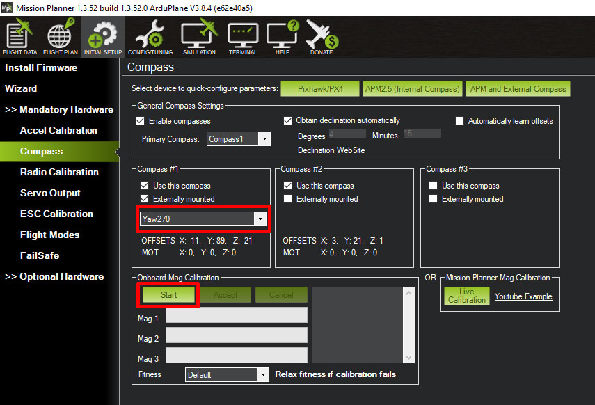
You must recalibrate the compass each time you move your UAV Mapper to a new flight location.
-
Start Mission Planner, Connect your UAV Mapper to Mission Planner and select
Initial Setup > Mandatory Hardware > Compass.
-
Select Pixhawk/PX4.
- Select Yaw270 (for
UAV Mappers with GPS/Compass mounted in the left wing with arrow
pointing to the left).
- Select the Start button.
- Rotate the airplane around all axis until the Mag 1 and
Mag 2
status bars reach SUCCESS.
- Select the OK button on the Reboot
autopilot window. Then reboot your Pixhawk.
Note:
Complete compass calibration documentation.
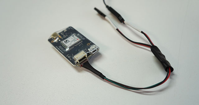
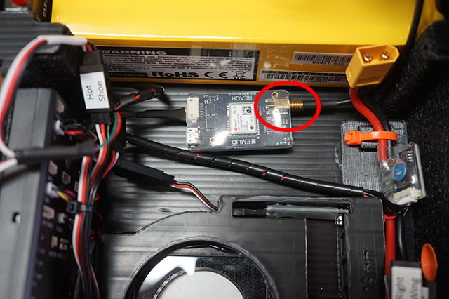
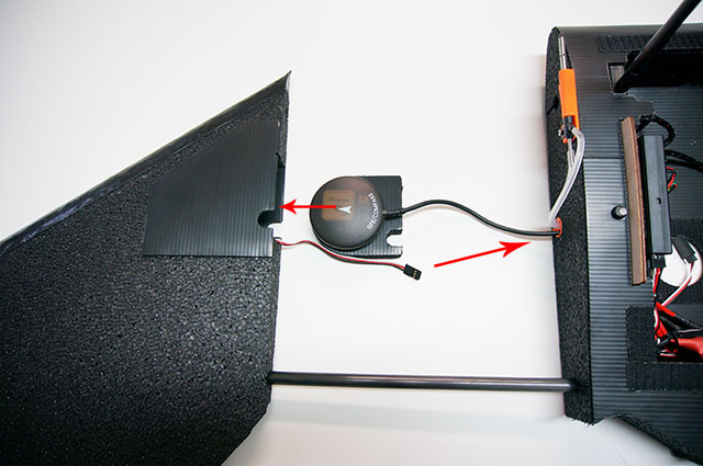
- Connect the DF13 6 pin connector on the Reach cable to the 6 pin connector OPPOSITE of the USB port
on the Reach module.
Once connected, leave the 6 pin connector in place. The board is
fragile. Disconnect from hot shoe and Pixhawk to remove the Reach module.
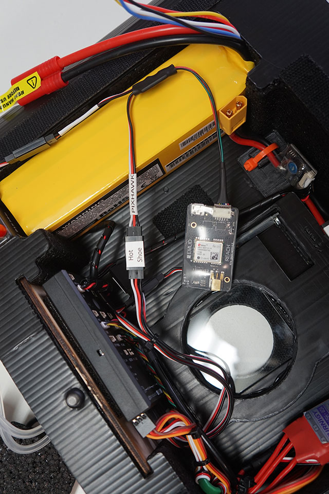
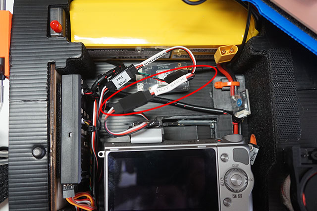
- Connect Pixhawk on the Reach cable to Hot
Shoe coming from the Pixhawk. This powers the Reach and the hot
shoe signal from the camera is sent to both the Reach and the Pixhawk.
This gives redundant geotags and allows Mission Planner to display
camera icons real-time when a picture is taken.
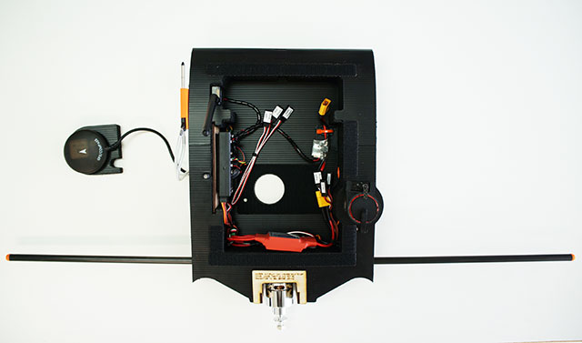
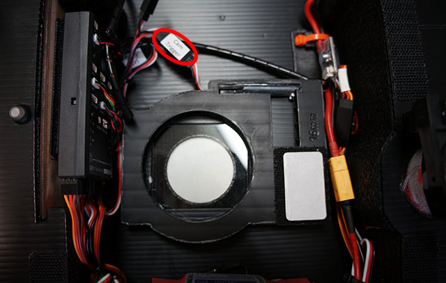
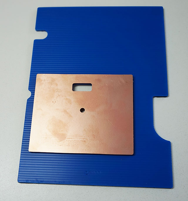
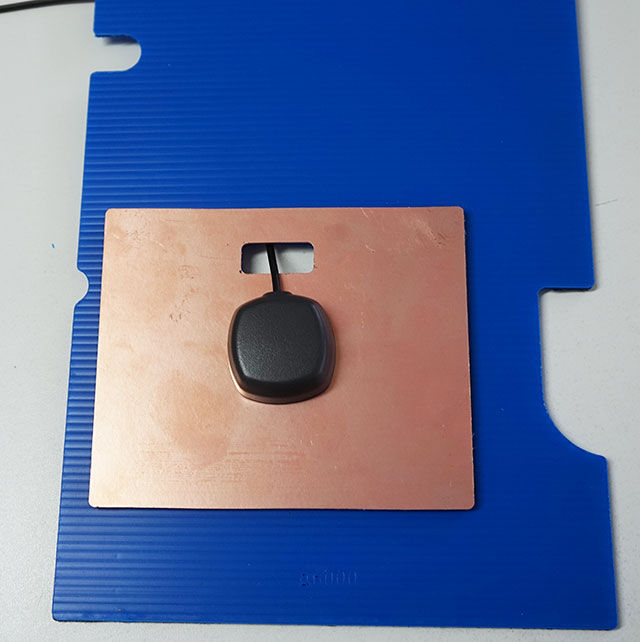
- Attach the ground plane to the body cover using the supplied Velcro.
- Stick the Reach antenna to the ground plane. Feed the antenna wire
through the ground plane and cover.
- Tidy up the antenna wire with a zip tie.
- Connect the antenna cable to the Reach module.
- Connect the hot shoe cable on the camera's hot shoe to Hot Shoe on the Reach cable.
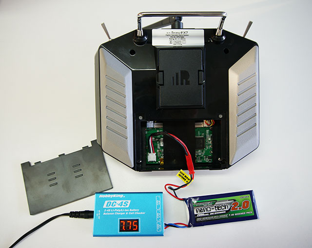
Charge the Taranis X7 battery
- The Taranis X7 does not have a charge plug. To charge, remove
the battery cover and connect the battery's charge plug to a Lipo
charger.
- Battery voltage is displayed on the Taranis X7 screen and should
be charged before it drops below 6.8 volts. Over discharging the
battery will damage it. Discharge battery to less than 7.6 volts for
storage.
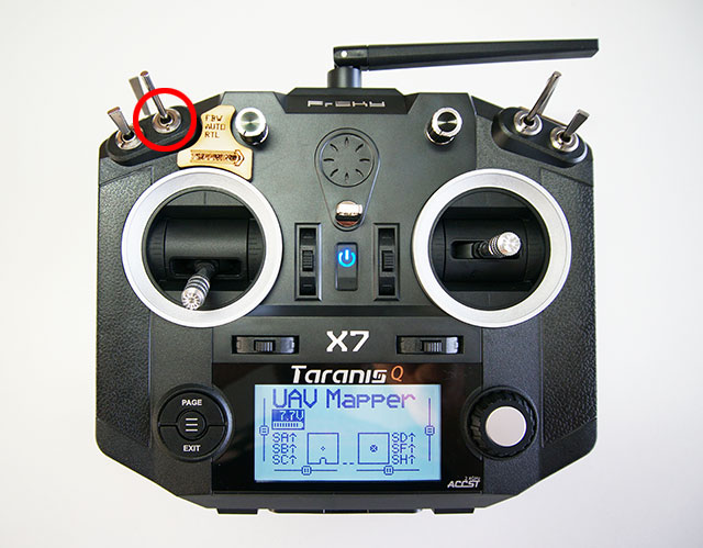
The UAV Mapper is preprogrammed with 3 flight modes
- Fly By Wire (FBW)
- Auto
- Return to Launch (RTL).
Flight modes are selected using the transmitter's switch
marked with the flight mode label.
-
FBW -
(Fly By Wire A) Standard
RC control with simple stabilization. If you let go of the sticks
your UAV Mapper will automatically return to level flight.
-
Auto
- Your UAV Mapper will follow the waypoints in the mission you have setup and uploaded to the Pixhawk.
-
RTL (Return to Launch)
- Your UAV Mapper will return to the location where it was armed and
circle at 100
meters above.
- Place your UAV Mapper on a level surface.
- Turn the transmitter on
- Select FBW on your transmitter flight mode switch
- Lower the throttle
- Connect your UAV Mapper battery
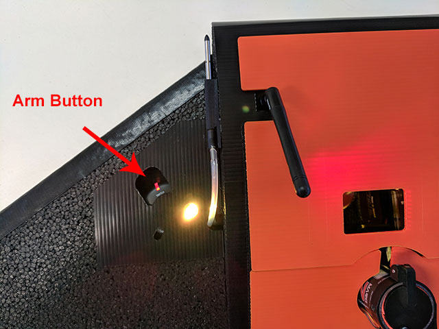
- Press the Arm button.
Left stick back: Motor off.
Left stick forward: Motor on full. Have a helper hold your UAV
Mapper.
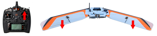
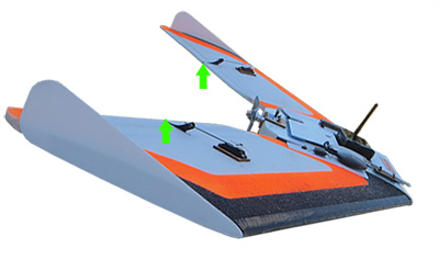
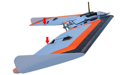
Right stick forward: Both elevons move 5/8" (16mm) down. UAV Mapper
pitches down.

Right stick back: Both elevons move 5/8" (16mm) up. UAV Mapper pitches
up.

Right stick right: Left elevon down 5/8" (16mm), right elevon up 5/8"
(16mm). UAV Mapper rolls right.
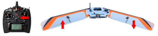
Right stick left: Left elevon up 5/8" (16mm), right elevon down 5/8"
(16mm). UAV Mapper rolls left.
Note: Set RC transmitter direction
here.
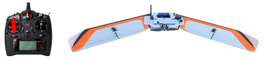
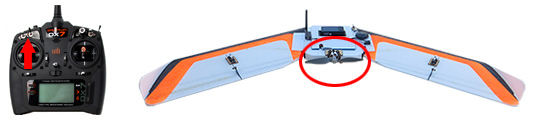
Always make sure the autopilot is behaving
properly before you fly. As you pitch and roll your UAV Mapper, the
elevons "fight back" to return the airplane to level.
- Place your UAV Mapper on a level surface
- Turn the transmitter on
- Select FBA on your transmitter flight mode switch
- Lower the throttle
- Connect your UAV Mapper battery
- Press the Arm button.
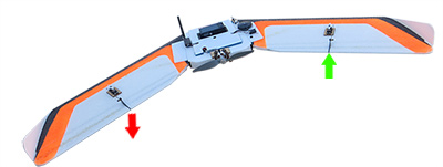
Roll UAV Mapper left: Left elevon down,
right elevon up.
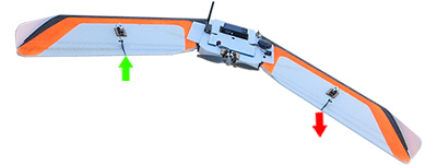
Roll UAV Mapper right: Left elevon up,
right elevon down.
Pitch UAV Mapper down: Both elevons up.
Pitch UAV Mapper up: Both elevons down.
Note: Set Pixhawk response
here.
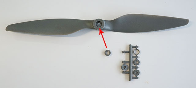
- Install the 6mm adapter ring.
Included with your propeller when purchased through Tuffwing. APC part number
LPAR06E.
IMPORTANT: Failure to use an adapter ring will result in vibration which may cause your UAV Mapper to crash during flight.
- Remove the nut and washer from the propeller shaft.
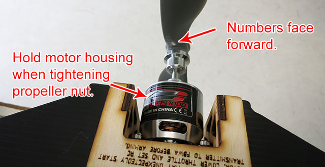
- Slide the propeller onto the shaft. Make sure the numbers face towards the front of the
airplane.
- Hold the motor housing tight while you tighten the propeller
nut. Failure to adequately tighten the nut will result in the propeller
spinning freely.
Caution - Never arm your UAV Mapper with the propeller
installed unless you are ready to fly.
Always remove the propeller during any diagnostics.
The motor can unexpectedly start if a fail safe condition occurs
such as no RC receiver.
Only Arm with propeller on if RC transmitter is on, throttle down,
and Flight Mode set to FBW.
Turn on your transmitter and set your flight mode switch to
Stabilize.
Connect your UAV Mapper battery.
The UAV Mapper electronics bay cover has an LED viewing hole so you can
see the Pixhawk status during boot up.
Be sure to power up where you want your UAV Mapper to loiter when in RTL
mode.
 Pixhawk is booting up.
 Error. Most likely the Pixhawk Micro SD was removed to retrieve the flight log
and not replaced.
Error. Most likely the Pixhawk Micro SD was removed to retrieve the flight log
and not replaced.
 Pixhawk is waiting on GPS lock. Do not fly until green.
 Failsafe error. Do not fly.
 Pixhawk
has GPS lock and is ready to fly. Pixhawk
has GPS lock and is ready to fly.
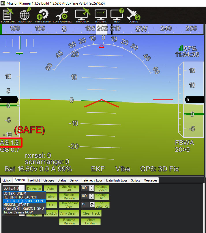
Clogged pitot tube or damaged tubing is one of the most common problems
with fixed wing UAVs. Always check your airspeed system before flying.
- Air Speed (AS) on the Flight Data screen should read between 1 and 3 while the UAV Mapper is stationary.
If airspeed is out of range then do a preflight calibration.
- Select the Actions tab > PREFLIGHT CALIBRATION.
- AS should now be 1 to 3 ms.
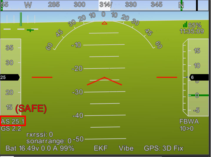
- Blow hard at the pitot
tube. Airspeed (AS) should increase to about 15
to 40. Do not fly if AS will not increase.
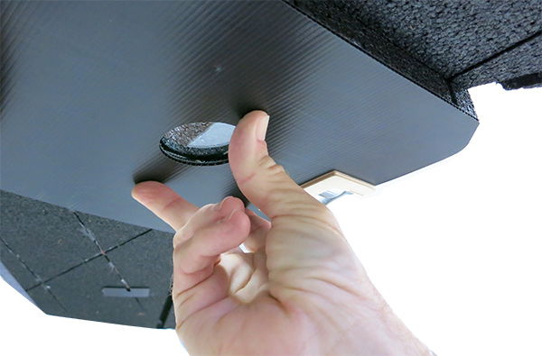
Your UAV Mapper has two balance holes on each side of the camera window.
Balance your UAV Mapper as shown. It is okay to balance or fall forward,
but it cannot fall back.
The most challenging part about flying a UAV Mapper, or any fixed wing
UAV is getting it down. Unlike Pixhawk guided copters, there's no built
in automatic land on a fixed wing. A copter can descend straight down,
while a fixed wing must approach on a clear glide slope. If you are not a
proficient RC pilot then you must create a landing pattern using Mission
Planner and upload it to your UAV Mapper. First, make sure your flying
site meets the minimum size requirements shown below, then create the
takeoff and land shown mission below.
- Start Mission Planner and select Flight Plan.
Important: Use Relative altitude, which sets the waypoint's altitude relative to where the Pixhawk is powered up.
Absolute is altitude above sea level,
and
Terrain requires use of the terrain following database.
- Click on the map to create WAYPOINT 1.
- Click on the map again to create WAYPOINT 2.
- Right-click on the map and select Takeoff. Enter 100(m) for
takeoff altitude. Enter 30 (degrees) for takeoff pitch.
- Use the Up button to move the TAKEOFF waypoint to the top. Verify Pitch Angle is 30 and Alt is 100.
- Set WAYPOINT 2 Altitude to 35m. This is your approach waypoint.
- Set WAYPOINT 3 to LAND and Alt to 0.
- Select WriteWPs to copy the mission to your UAV Mapper
IMPORTANT: Any mistake in this mission will result in a crash. You must
understand every step of this process. This is the foundation for
getting your UAV Mapper in the air and safely back to the ground.
There are two ways to deploy the parachute; with
the Parachute switch on the RC transmitter or as a
waypoint in a mission.
Parachute switch
The parachute can be deployed anytime with
with the Parachute switch on the RC transmitter. Note the following:
- FBWA flight mode: Throttle stick must be in the off position. In
this flight mode the motor will continue spin after the parachute
has been deployed if the throttle has not been lowered. This will
cut the parachute cord.
- AUTO and RTL flight modes: The motor will automatically stop
when the parachute is deployed.
- Your ESC must have "brake" enabled to stop the motor from
spinning when the throttle is lowered.
- If possible, deploy the parachute while the UAV is flying into
the wind and less than 15m (50') above the ground. The
parachute is heavily loaded and excessive speeds can result from
high falls.
Deploy parachute at the end of a mission
Add the following to the end of your mission to
automatically deploy the parachute:
- Create a
mission.
- Select your last WAYPOINT and then click the Add Below
button.
- Change WAYPOINT to DO_PARACHUTE.
- Change Enable to 2. Your parachute will now
deploy immediately following the last waypoint
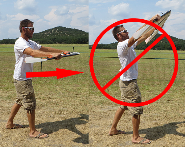
- Move to a spot in your flying field with 400 ft (120m) of clear
space ahead, into the wind.
- Set your transmitter to Stabilize (or FWB) mode, make sure
the throttle is down, and press the arm button
until it's solid red.
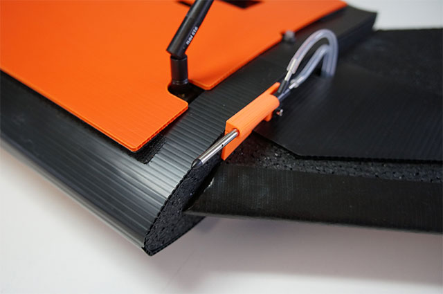
- Hold your UAV Mapper like the photo below.
Be prepared for the motor to start
full throttle.
- Have a helper switch the flight mode switch to
Auto. This will execute the waypoint mission you
have uploaded.
Caution - The propeller will spin immediately. Be prepared.
There is no delay. The motor will remain full throttle until
take off altitude is reached or the flight mode switch is
changed to FWBA.
- Pitch and roll your UAV Mapper to make sure
control surfaces are properly moving.
- Face into the wind and hand launch your UAV Mapper as shown above. The
toss should be a few degrees above level.
Note: You can stop the motor and abort the takeoff by switching the flight mode switch to FWBA.
Caution - Do not wear loose clothing while launching your UAV
Mapper. Especially loose sleeves that can snag on a servo and
cause a dangerous failed launch.
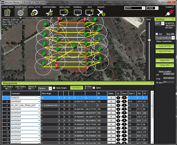
Aerial photography missions are trivial once you've
mastered take off and landing missions. Camera connection information
can be found under Tuffwing Support. Do the
following to create a typical UAV Mapper photo mission.
- Start Mission Planner, select
Flight Plan, right-click on the map and select
Draw Polygon > Add Polygon Point.
- Add additional Polygon points to create a border around the area you
want to photograph.
- Right-click on the map and select Auto WP > Survey (Grid).
- Select the Simple tab and set the following:
- Camera: Select the camera you are
using.
- Altitude: 100m
- Angle: This rotates the flight line. You want to fly cross
wind. This site typically has a south wind, so the flight lines
are East-West.
- Camera top facing forward: Check.
- Flying Speed & Use flying speed: Leave unchecked. If checked
it will override the default flying speed. However, you should
enter 17ms Flying Speed for flight
statistic shown at the bottom of the screen.
- Add Takeoff and Land WP's: Check
- Use RTL: If you need to Auto-land, then
leave unchecked. If you prefer to have your UAV Mapper Return to
Launch and loiter overhead upon mission complete and land
manually, then check.

- Select the Grid Options tab and set the
following
- OverShoot [m]: to 80 on both ends. Your UAV
Mapper can't turn tight enough to get back on the line.
- Start From: Set this to the furthest down
wind corner of your survey area. You want your UAV Mapper to
start downwind and work its way up wind, while flying cross
wind. This keeps the ground speed low and turns tighter.
- Overlap [%] 80. This sets how frequently
the shutter is triggered.
- Sidelap [%] 80. This sets how close the
flight lines are.
- Select the Simple tab and then Accept.
- Modify take off and landing
- Update TAKEOFF parameters. Alt
must be at least 100.
- You must have an approach WAYPOINT, 35m
Altitude, 600 ft (120m), down wind, from your LAND waypoint.
You can right-click on the map to insert waypoints and use
the Up Down arrows to move the waypoints.
- Select Write WPs to copy the mission to your UAV Mapper.
This product contains copyrighted software licensed under GNU
General Public License v3 (GPLv3). Please see
http://firmware.diydrones.com/for
further information and a copy of the license.
This product contains copyrighted software licensed under the
BSD License. Please see
https://github.com/PX4/Firmwarefor
further information and a copy of the license.
This product contains copyrighted Open Source Hardware licensed under
the Creative Commons Attribution-ShareAlike 3.0 Unported (CC BY-SA 3.0).
Please see https://github.com/PX4/Hardware for
further information and a copy of the license.
Errata, kudos brian.christal@gmail.com
|


